Axially and Radial Corrugated Horns
Figure 1 22 dB Gain Horn with 8 axial and 26 radial Corrugations CHAMP Model
The axial corrugations may be combined with normal vertical corrugations to shorten the horn axial length [1]. Figure 1 shows a horn designed with an initial axially corrugated section at a cone angle of 30° followed by a linearly tapered normal corrugated section. The design goal was to achieve 22 dB of gain and compare it to a normal corrugated horn length designed in an example above. The normal horn with S = 0.2 is 12.6λ long while this horn is only 5.8λ long. While the linearly tapered horn has 100 corrugations, the bowl horn has 8 axial corrugations and 26 vertical ones. Constant depth slots were used for the bell in the design and gave acceptable performance. The excellent cross polarization performance was achieved by optimizing the depth of the axial slots using CHAMP (TICRA), a mode-matching plus BOR-MoM code, while the length and aperture sizes of the bell were designed to achieve the desired gain [2].
The report Axially and Radial Corrugation Horns presents a series of designs ranging from 18 dB to 25 dB.
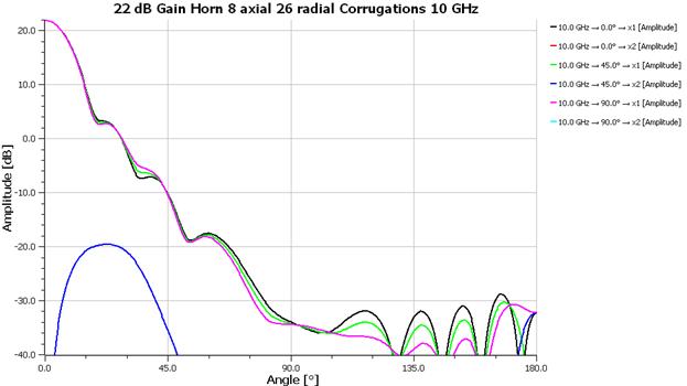
Figure 2 22 dB Gain Horn with 8 axial and 26 radial Corrugations 10 GHz
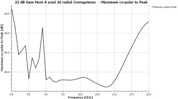
Figure 3 22 dB Gain Horn with 8 axial and 26 radial Corrugations Cross Polarization
10 dB Half Beam Width = 13.3̊ Phase Center = 65 mm
[1] Jorge Teniente, et al, Choked Gaussian Horn: Extremely Low Sidelobe Compact Antenna Design, IEEE AWPL, vol. 1, 2002, p. 200 – 202.
[2] Jorge Teniente, et al, Low Sidelobe Corrugated Horn Antennas for Radio Telescopes to Maximize G/Ts, IEEE AP-S Trans., vol. 59, No. 6, June 2011, pp. 1886 – 1893.