7-3.3 Axially Corrugated Horns [17b]
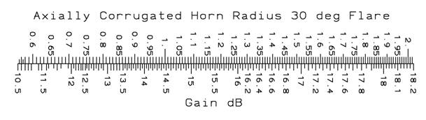
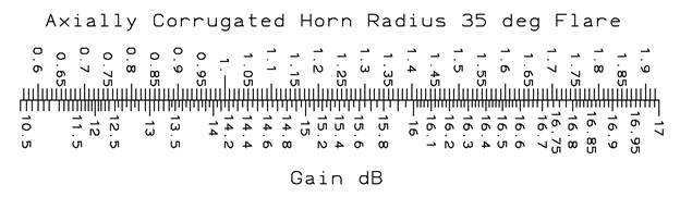
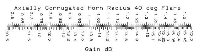
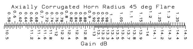
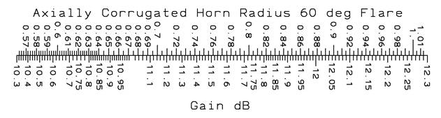
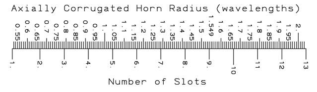
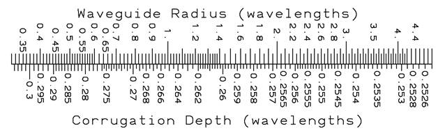
Low gain horns can be designed using a wide bell flare angle and circular choke corrugations coaxial with its axis. Figure 7-ab gives the geometry of these corrugations. The 30° flare horn has a range from 10.5- to 18.4-dB gain. The gain ranges from 10.5 dB to 14.5 dB for θ = 45° and 10.3 dB to 12.4 dB for θ = 60° for realizable designs. The antenna has good patterns over an entire waveguide band without applying optimization. The downloadable DOS prompt executable axialcc computes dimensions given desired gain and half slant angle. A full report can be downloaded axially corrugated horns using CHAMP (TICRA) analysis. The horn aperture radius is given in wavelengths in the scales below.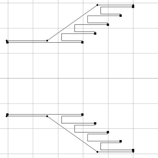
Figure 7-ab Axially Corrugated Horn Geometry
17b. Christophe Granet, et al, Chapter 3 Aperture Antennas: Waveguides and Horns, Modern Antenna Handbook, Wiley, 2008, p. 127f.
These designs have an input waveguide radius is given by ![]() , a pitch-to-width ratio of 0.8, and the approximate pitch is λ/8. In CHAMP it is necessary to include the analysis of the horn exterior using the BOR-MoM analysis since currents are excited on the exterior. Without exterior analysis incorrect results are obtained.
, a pitch-to-width ratio of 0.8, and the approximate pitch is λ/8. In CHAMP it is necessary to include the analysis of the horn exterior using the BOR-MoM analysis since currents are excited on the exterior. Without exterior analysis incorrect results are obtained.
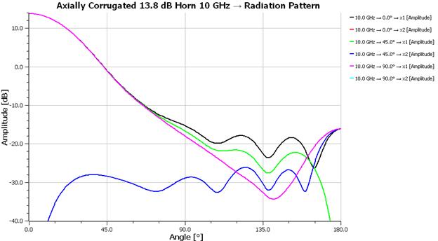
The cross polarization in the diagonal plane can be improved by optimizing on the four slot depths in CHAMP. The cross polarization improves by 9 dB and the beams are more nearly equal.