Directivity of Microstrip Patches on Ground Plane
Full write-up for 3rd edition is given Directivity of Microstrip Patches including finite ground planes.
The directivity of a microstrip patch can be found from the cavity models of patches and integrated over the hemisphere to compute directivity. We obtain the same directivity for linearly and circularly polarized patches because a circularly polarized patch is a linear combination of two linearly polarized patterns. Integration over all values of Phi produces the same integral for both cases.
Table 6-1 [1, p. 290] lists the directivities computed for a large ground plane. The values are only given at 0.1 dB increments because closer values are unnecessary. In an actual application the microstrip patches will be mounted on a finite ground plane and the values will change. Table 6-1 is sufficient for estimates. Table 6-1 has been reduced to Scales 6-1 and 6-2 that give directivity of the patches and the corresponding substrate dielectric constant. These are interpolated from tables of maximum magnetic current given size [2, pp. 80-92]
Table 6-1 Estimated Directivity of Square and Circular Microstrip Patches on a Large Ground Plane.
Dielectric Constant |
1.0 |
2.0 |
3.0 |
4.0 |
6.0 |
8.0 |
10. |
16. |
Square Patch (dB) |
8.4 |
7.7 |
7.2 |
7.0 |
6.7 |
6.5 |
6.4 |
6.3 |
Circular Patch (dB) |
9.8 |
7.6 |
6.7 |
6.2 |
5.8 |
5.5 |
5.4 |
5.1 |
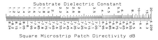
Scale 6-1 Estimated directivity of square patch on a large ground plane for either linearly or circularly polarized antenna
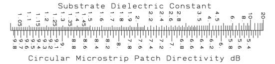
Scale 6-2 Estimated directivity of circular patch on a large ground plane for either linearly or circularly polarized antenna
Least squares approximations to Table 6-1 can be computed. We use the variable: ![]() . For a square patch we calculate the following approximation for directivity.
. For a square patch we calculate the following approximation for directivity.
![]()
A circular patch on a large ground plane has a similar equation.
![]()