7-9.1 Potter Horn
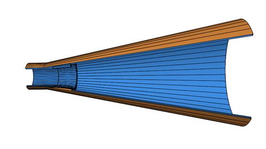
Figure 7-9.1-1 3-d Diagram of 20 dB Potter Horn
Figure 7-9.1-1 shows the design for a dual mode circular waveguide horn to generate the hybrid mode [37a].
An initial waveguide step at the input generates the TM11 mode at the correct level for a hybrid mode. This horn was design empirically over the range from 13- to 24-dB and a series of design curves was produced [37a]. These designs start with an input waveguide radius, ai = 0.51λc and a step radius, as = 0.65λc.
Starting with these dimensions, an optimization within a mode-matching analysis, examples: CHAMP (TICRA) or Mician MicroWave Wizard, quickly produces a design with desired parameters. However, the design equations will produce a design very close to the desired gain that radiates in the hybrid mode with low cross polarization in the diagonal plane. A horn designed for 20 dB gain had an 8% 25 dB cross polarization bandwidth and 14% at 20 dB. Horns design with lower gains had similar bandwidths to the 20 dB case.
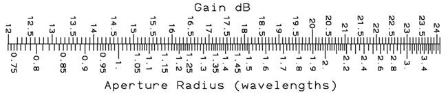
Potter Horn Aperture Radius versus Gain
Potter Horn Axial Length from Step given Aperture Radius
Potter Horn 10 dB Beamwidth versus Aperture Radius
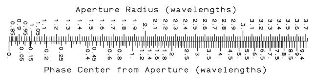
Potter Horn Average Phase Center given Aperture Radius
A longer report along with a CHAMP test input file can be downloaded Step_Multi-mode_horns.zip.
18.0 dB Gain Potter Horn Response
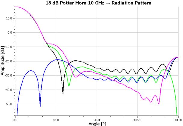
18 dB Gain Potter Horn Center Frequency Pattern (10 GHz)
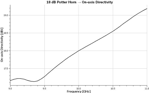
18 dB Gain Potter Horn Directivity versus Frequency
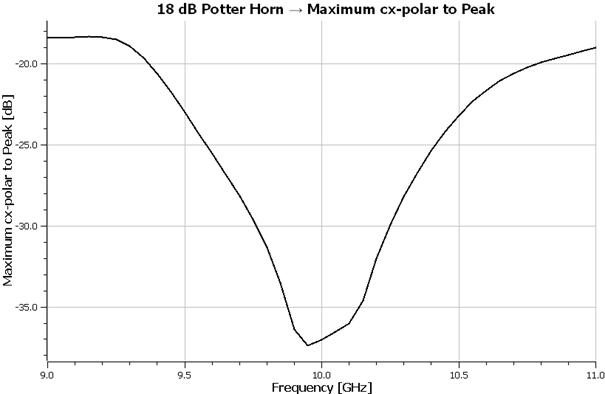
18 dB Gain Potter Horn Maximum Cross-Polarization relative to Peak versus Frequency
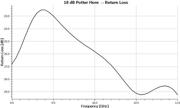
18 dB Gain Potter Horn Return Loss relative to Peak versus Frequency