7-9.3 Turrin Horn[37b]
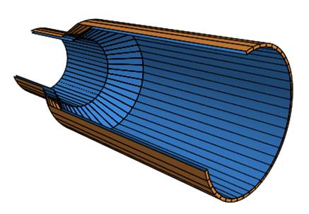
Figure 7-9.3 Turrin Horn
The Turrin horn starts with a short conical section with a cone angle of 23° to 30° and then is followed by a cylindrical section to phase the relative response of the TM11 generated by the transitions to generate the hybrid mode. The original article only gives a notional design procedure that relies on empirical parameter adjustment. The optimization portion within mode-matching analysis program CHAMP was used to produce the design table below. The Turrin horn radiates hybrid mode patterns over the range of 11.5- to 13.1-dB. The optimization parameters were the length of the conical and output cylindrical sections. The currents excited on the external surface of the horn must be included in the optimization because of the low gain. The bell cone angle was calculated from the output dimensions.
Table 7-9.3 Turrin Horn Designs, λc, ai = 0.477 λc
Outer Radius, λ |
Gain dB |
10dB |
Conical Length, λ |
Cylindrical Length, λ |
Cone |
Cross |
0.62 |
11.46 |
95.5 |
0.3522 |
1.0787 |
22.0 |
32 |
0.64 |
11.54 |
94.6 |
0.5212 |
1.1637 |
17.7 |
32 |
0.66 |
11.67 |
93.3 |
0.4224 |
1.5411 |
23.4 |
41 |
0.68 |
11.51 |
95.1 |
0.4220 |
1.6939 |
25.7 |
33.1 |
0.70 |
11.99 |
89.7 |
0.4477 |
2.0458 |
26.5 |
39.2 |
0.72 |
12.00 |
89.6 |
0.4754 |
2.1293 |
27.1 |
43.2 |
0.74 |
12.31 |
86.4 |
0.5592 |
2.2470 |
25.2 |
36.4 |
0.76 |
12.45 |
84.9 |
0.5193 |
2.5886 |
28.6 |
43.7 |
0.78 |
12.62 |
83.2 |
0.5847 |
2.7213 |
27.4 |
50 |
0.80 |
12.80 |
81.4 |
0.6084 |
2.9008 |
28.0 |
42 |
0.82 |
12.94 |
80.1 |
0.5829 |
3.1436 |
30.5 |
50 |
0.84 |
13.12 |
78.3 |
0.6152 |
3.2341 |
30.5 |
40 |
The antenna has about a 10% 25-dB cross polarization bandwidth. The long length of the output cylinder required to phase the two modes to form the hybrid mode causes narrow bandwidth. The response shows narrow frequency regions of quickly varying parameters. The Scrimp horn has a wider bandwidth and smaller size.
A longer report along with a CHAMP test input file can be downloaded Step_Multi-mode_horns.zip.
0.72λ Outer Radius Turrin Horn
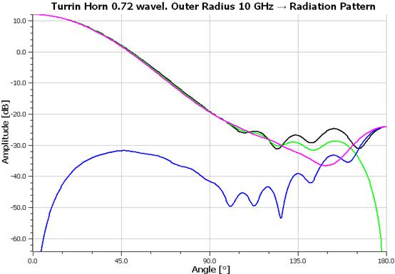
0.72λ Outer Radius Turrin Horn Center Frequency Response (10 GHz)
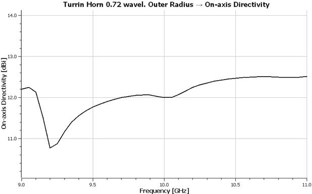
0.72λ Outer Radius Turrin Horn Gain versus Frequency
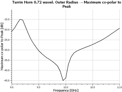
0.72λ Outer Radius Turrin Horn Maximum Cross-Polarization relative Peak versus Frequency
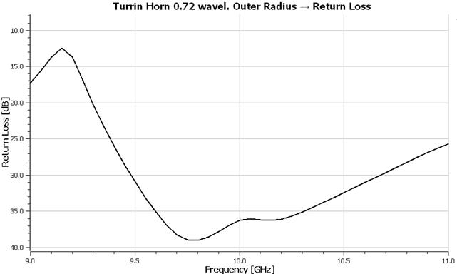
0.72λ Outer Radius Turrin Horn Return Loss versus Frequency